DESIGN CONSIDERATIONS FOR THERMAL MANAGEMENT OF POWER SUPPLIES
The increasing performance and integration of electronic components has not only enabled greater equipment functionality but often delivers this in smaller and smaller form factors. Associated with this trend is the expectation that power supplies will also become more compact. Initially this demand was addressed by the adoption of switch-mode technology but the continuing trend has led to increased power densities. Part of the remedy for this is to use higher switching frequencies and more efficient designs. However, the inescapable conclusion is that there will always be a need for effective thermal management in power electronics.
To appreciate this we first need to understand the intrinsic conversion efficiency of a power supply’s design and how the resulting losses, dissipated as heat, can best be dealt with. The key is to ensure that both the power supply and the equipment it is powering can continue to operate reliably over their rated temperature range. And while efficiency in both electrical and thermal management terms is clearly important, dependable performance in regard to product reliability is an absolute must. Therefore, designing to mitigate potential failures caused by thermal stress is vital. This paper will first consider the basics of how efficient heat dissipation relates to power supply performance, and how thermal stress affects reliability, before looking in more detail at the evolution of methods for improving thermal management.
POWER EFFICIENCY AND THE CHALLENGE OF HEAT DISSIPATION
In an ideal world all the energy input to a power supply would be converted to usable electrical power at the output. Unfortunately real life systems incur losses and in a power supply some energy is consumed by the internal electronics and converted into heat. Key components that contribute to such losses are: transformer cores and windings, power switches, current sense resistors and filter capacitors with significant ripple current.
Consequently:
Often the power dissipated in a power supply is not directly stated but instead given indirectly in terms of its efficiency, which is the ratio of output power to input power where:
Hence, knowing the efficiency of a given power supply design and the required output power we can calculate this power loss, or power that must be dissipated as heat, as:
This calculation needs to be done under worst case load conditions i.e. for the maximum anticipated load power. Clearly higher efficiencies equate to less heat that will need to be dissipated, easing the problem of removing this heat from the supply. Nevertheless appropriate thermal management is still vital and can have a direct impact on the performance of a power supply. For example, electronic circuits often perform more efficiently at lower temperatures and will in turn tend to dissipate less energy as wasted heat. The efficiency gains that can be obtained through effective cooling increase significantly as the power output of the overall system increases. Higher temperature operation can also have an effect on reliability and systems that run cooler will have a lower probability of failing within a given time, as explained more fully in section 2. These factors make it important to consider all possibilities when looking at the cooling options for power supply designs.
There are three basic mechanisms by which heat is dissipated from electronic components such as those found in a power supply:
Radiation
Radiation through electromagnetic emission provides one means by which heat transfers between elements at different temperatures, so a transformer might radiate heat to the surrounding case of the supply. The calculation of radiant heat transfer is complex and affected by many factors such as the spacing between elements and the color and finish of surfaces, not just the temperature differential. Added to which, and perhaps fortunately, this form of heat loss is rarely the primary means of dissipation.
Conduction
Conduction is the transfer of heat through contact with another solid material. Metals are generally good conductors of heat. When heated, electrons in the structure of the metal separate from their atoms leaving the ions to vibrate with a kinetic energy that is greater the hotter the metal is. This kinetic energy is transferred from hotter to cooler parts of the metal by the flow of electrons that collide with ions as they move, until they are recaptured once they lose enough energy. The rate of heat flow depends on the temperature differential, or gradient, and the thermal conductivity of the material.
Within a power supply, heat is readily conducted from a component such as a resistor through the printed circuit board (PCB), with its high copper content, to the supply’s metal enclosure. Further conduction through the equipment’s PCB main board or system chassis may also remove heat from a power supply although, traditionally, this has been considered less effective than convection cooling, which will be examined in the following section.
Calculating heat transfer for conduction cooling is usually expressed in terms of thermal resistance rather than thermal conductivity, which is its reciprocal. Thermal resistance, measured in °C/W, is defined as:
Where:
- ΔT is the temperature difference in °C
- Q is the heat flow in watts
Different nomenclatures may be used to denote the thermal resistance between different points in a system e.g. for a power transistor the resistance between the semiconductor junction, where the heat is generated, and the device’s case might be referred to as θJC while the thermal resistance from the case to the ambient air would be θCA. The combined thermal resistance from the conduction and convection heat flow paths simply sums to give θJA = θJC + θCA. The inclusion of a heat sink can also be modeled, allowing for the thermal resistance of any heat transfer pad (or thermal compound), by substituting the thermal resistance from heat sink to ambient for the case to ambient figure.
Convection
Convection is defined as the transfer of heat via a fluid, which can be a liquid but is more typically air. If the fluid flow results from the gravitational forces on the fluid as its density varies (i.e. warm air rises), it is referred to as natural or free convection. However, if the fluid flow is created by external means such as fans or blowers, it is referred to as forced convection.
Consequently, convection provides one of the main pathways for heat to be transferred away from the power supply as energy is transferred from the solid components of the system to the air as it moves past. As the rate of heat dissipation is proportional to the airflow rate, forced-air cooling will provide a greater degree of cooling than free convection. However while forced-air cooling provides a steady flow of cooler air to transfer heat away from a power supply it does incur the penalty of contributing acoustic noise to the system and its immediate environment. In addition, fans will increase power consumption within a system and can reduce overall lifetime of the application with the introduction of additional mechanical parts that may fail.
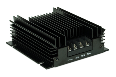
The efficiency of cooling by convection can be improved with a heat sink that uses conduction to increase the surface area of a device that is in contact with the surrounding air, as is done with CUI’s VHK series dc-dc converter shown in figure 1. To maximize conduction from the heat generating components to the heat sink, the use of a thermal compound is recommended to fill any void between the devices to be cooled, which may be a complete power converter, and the heat sink surface. Bolts or clamps that increase contact pressure also help to improve thermal transfer into the heat sink.
To size a heat sink for a given application it is necessary to know how much heat needs to be dissipated (the heat flow Q as defined earlier), the maximum ambient temperature (TA) and the maximum allowable case or baseplate temperature (TC) of the power supply. Hence the required thermal resistance for the heat sink must be no greater than:
THERMAL STRESS AFFECTS POWER SUPPLY RELIABILITY
It is not possible to predict with precision or any certainty for how long a specific power supply will operate or after how many hours it will fail. However, the standard practice for electronic and mechanical components and systems is to use probability analysis to determine, with reasonable confidence, the expected lifetime or likelihood of failure. The failure rate for a component or system is usually expressed as a frequency, e.g. failures per hour, and usually denoted by the symbol λ.
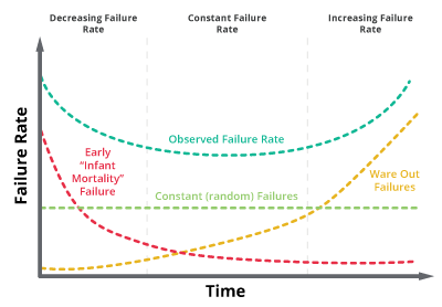
The actual failure rate however typically varies over the life of equipment due to factors that can be attributed to ‘early life failures’, ‘random failures’ or ‘wear out failures’. The cumulative characteristic that results from this is commonly referred to as the ‘bathtub curve’, shown in figure 2.
A supply’s reliability is a function of multiple factors: a solid, conservative design with adequate margins, quality components with suitable ratings, thermal considerations with necessary derating, and a consistent manufacturing process. Reliability, or the probability of a component not failing before a given time, can be calculated with the following formula:
Sources of Stress
Power supply life is affected by three kinds of stress: thermal, mechanical, and electrical. Of these, thermal stress is the most challenging and insidious stress, because it manifests itself in so many ways. As we have seen, by their nature, supplies dissipate heat: a 1000 W supply operating at an admirable 90% efficiency is still producing over 100 W of heat. But it is not just the supply’s own dissipation which causes the supply to operate at higher temperatures. Most of the power that the supply provides to the electronics eventually ends up as dissipated heat within the enclosure as well (some may be used outside the box to drive loads such as motors) thus adding to the overall thermal load and heat rise of the product.
Thermal stress takes two forms: static and dynamic. Static thermal stress means operation at elevated temperatures, which degrades components and their basic materials. Bulk capacitors may begin to dry out, or their seals may break down; similarly resistor coatings may begin to deteriorate and connector expansion can result in contact mismatch.
Dynamic thermal stress is associated with heating and cooling cycles, which occur as the supply output goes from full load to low load, or is turned on and off. Each time this happens, device structures and connections expand and contract, allowing micro-cracks to develop due to the differing coefficients of thermal expansion between materials. Such repeated cycling ultimately causes outright breaks and failures. However, it is difficult to estimate the deterioration in product reliability due to dynamic stress because the heating and cooling rates of these cycles also affect their impact.
The Effect of Temperature on Component Life
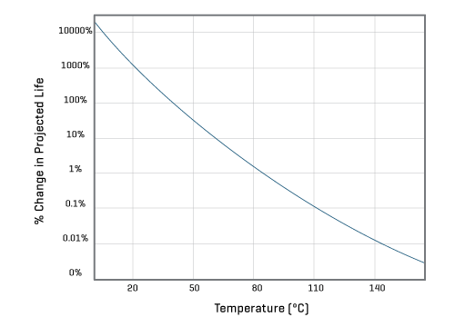
Usage temperature has a significant effect on reliability as illustrated in figure 3. This effect is based on chemistry’s Arrhenius equation which is typically used to model the acceleration of temperature dependent physical processes that lead to functional wear out.
Arrhenius Equation
Where:
- CR is the “Process Rate Coefficient”
- M is an experimentally determined constant specific to the materials/methods used
- e is Euler’s number (2.718281), the base of the natural log
- Ea is the activation energy for the processes that lead to failure (typ. 0.8eV to 1.0eV)
- k is the Boltzmann constant 8.617x10⁻⁵ evK-1
- T is temperature (°K), typically at ambient room temperature (25°C / 298°K)
The effect of a given temperature change on a component’s projected life can be measured using a small modification to calculate the acceleration factor:
Where:
- T1 is the reference temperature (e.g. 85°C / 358°K)
- T2 is the actual use temperature
- M is eliminated as it is the same at both temperatures
If we use an assumed Ea of 1.0 for a component designed to run at 85°C, we can calculate the effect (1/AR) on the projected life of the component.
| Temp °C | Temp °K | Acceleration Factor | Projected Life |
|---|---|---|---|
| 25 | 298 | 0.001473 | 67906% |
| 45 | 318 | 0.01701 | 5878% |
| 65 | 338 | 0.1471 | 679% |
| 85 | 358 | 1 | 100% |
| 105 | 378 | 5.550 | 18% |
| 125 | 398 | 25.93 | 4% |
This table shows clearly that minimizing temperature rise is the most direct way to increase reliability. Avoiding temperature cycling is also important, all of which calls for carefully planned thermal management via one or more of the cooling modes: convection, conduction, and radiation.
THE RIGHT DESIGN CHOICES DELIVER IMPROVED THERMAL MANAGEMENT
Extracting heat from a power supply can be dramatically enhanced by the right choice of materials and structure for its design. For example, providing efficient cooling via conduction through the baseplate is ideal for systems where active cooling through the use of fans is not desirable; such as professional-audio systems, which often need to be installed in areas where acoustic noise generated by electronic equipment cannot be tolerated. Elsewhere a suitably vented PSU case will allow the ready circulation of air for either natural or forced convection cooling.
When considering the choice of power supply for a system design the use of higher efficiency units or supplies that will be operated below their full rated load can pay dividends. In the first instance, a 300 W power supply operating at full load with an efficiency of 85 percent will dissipate 53 W in heat, whereas a 90 percent efficient supply will waste 20 W less in power converted to heat, potentially reducing or even eliminating the need for airflow-based cooling. In general, running a supply below full load will allow it to be operated at higher ambient temperatures where the rate at which heat can be removed from the vicinity of the power supply is reduced, or where the system requirements make it impossible to provide full forced-air cooling.
IMPROVING HEAT DISSIPATION THROUGH AIRFLOW
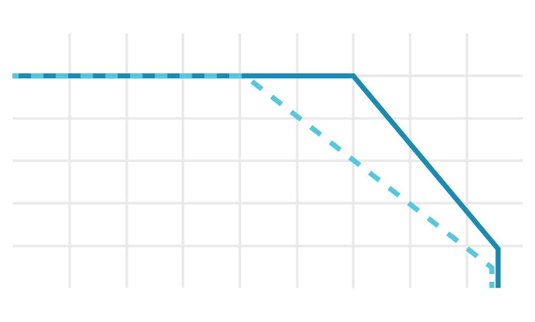
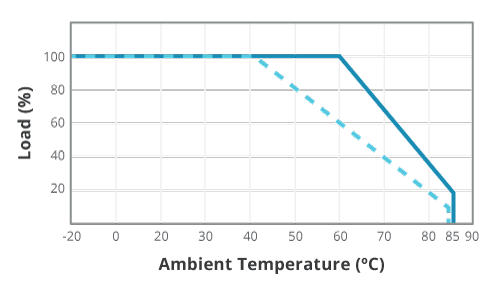
Power supply datasheets provide derating curves that show how much the output power needs to be reduced for either a given increase in temperature or a reduction in airflow. Forced-air cooling has a significant effect and allows a supply to operate at full power in higher ambient temperatures.
In general, forced-air cooling requirements will be expressed in cubic feet per minute (CFM) or linear feet per minute (LFM). For example, the derating curve of one CUI power supply, is highlighted in figure 4. It is both baseplate and forced-air cooled. Figure 4 shows that increasing the airflow to 10 CFM enables the enclosed version of this supply to operate at 100 percent of full load at an ambient temperature of 60°C. This compares to a derated output of 60% of full load when the same supply relies on just natural convection. Note also that the open-frame version of this supply only achieves 100% of full load output up to 50°C, illustrating the further effect that the mechanical design of a power supply has on thermal management.
When designing forced-air cooling, the fan should be sized to the cross-sectional area of the power supply within the enclosure to ensure the necessary velocity of air passes over the surface of the components. In general, air should be directed along the long axis of the power supply. However, a further consideration is the layout of any internal heat sinks. The fins of the largest of the heat sinks should run parallel to the direction of airflow. Also, airflow will be restricted by obstructions and there are often many large, and tall components mounted inside power supplies that will impede airflow. To prevent pressure from building up and to reduce the efficiency of the fan, the exit port for the air should be at least 50% greater in area than the entry port.
It can make sense for the fan to be sized larger than necessary as a larger fan can deliver a greater amount of cooling air but at a lower speed than a smaller fan. By running slower the fan will run more quietly, which can be crucial in applications where acoustic noise is a factor but conduction or natural convection does not provide sufficient cooling.
The orientation of the power supply within the system can also have an effect on cooling performance depending on the layout of the internal components. Because hot air tends to rise, a vertically mounted power supply will tend to transfer heat to other components whereas the hot air in a horizontal design will be pushed more easily towards the exit vents by convection or forced-air cooling.
Establishing the airflow (Q) that a fan must provide will depend on the temperature difference (ΔT) between the ambient temperature and the maximum operating temperature of the supply, and the total power (W) that must be dissipated (which may need to include not just the power lost due to the supply’s inefficiency but also heat dissipated within the electronics of the system if the fan is being used to cool the entire equipment).
SUMMARY
As we have seen, the system designer has a number of options available when considering the thermal management of the power supply and the surrounding system. While effective, forced-air cooling is not always the ideal choice for system designers. By trading off power supply capacity against load, by selecting higher-efficiency designs or by moving to advanced products that employ conduction cooling, it is possible to achieve high performance with little to no acoustic noise through the use of non-forced air cooling. Alternatively, fans can be selected that minimize noise emissions and which provide thermal compatibility over a wide ambient temperature range.
